Circuit Diagrams Symbols And Meanings

Símbolos Eléctricos y Electrónicos motor
Sample Circuit Diagram using symbol for a motor . Force and Motion Circuit symbol for a motor
Circuit Diagram Motor Symbol
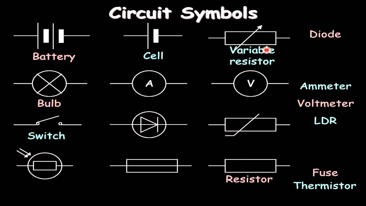
Electric circuits can be described in a variety of ways. An electric circuit is commonly described with mere words like A light bulb is connected to a D-cell . Another means of describing a circuit is to simply draw it. A final means of describing an electric circuit is by use of conventional circuit symbols to provide a schematic diagram of the circuit and its components.
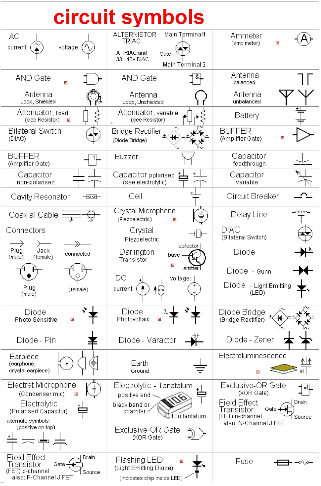
Electronic circuit, componnent data, lesson and etc…. circuit symbols
One-line diagram - a diagram that uses single lines and graphic symbols to indicate the path and components of an electrical circuit. One-line diagrams are used when information about a circuit is required but detail of the actual wire connections and operation of the circuit are not. Line Diagrams
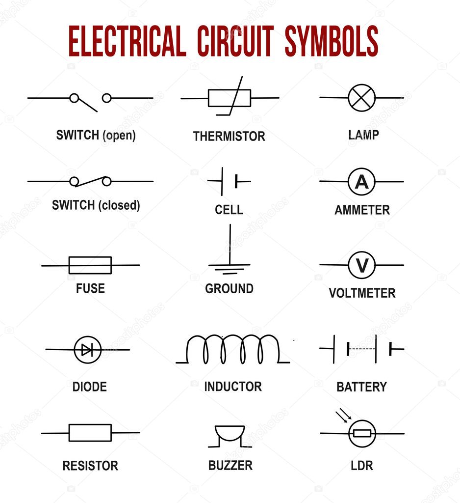
Electrical circuit symbols on white background (Helpful for basic Education & Schools), vector
Battery Circuit Symbol. A battery has more than a cell and is used for the same purpose. The smaller terminal is negative and the larger one is positive. Abbreviated as 'B'. DC Supply. DC Supply Circuit Symbol. Used as a DC power supply, that is, the current will always flow in one direction. AC Supply.
Circuit, circuitry, diagram, motor, science icon Download on Iconfinder
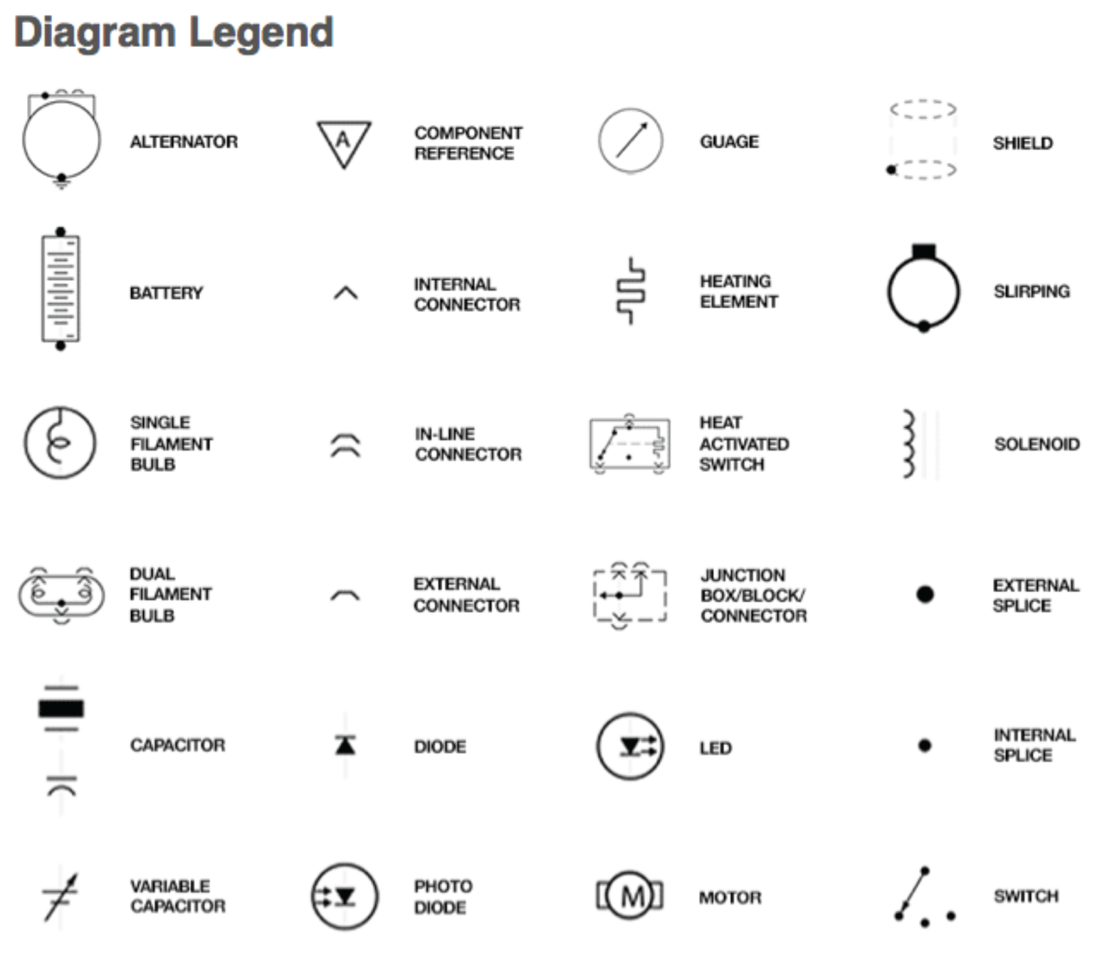
Circuit Symbols The following are the circuit symbols commonly used in motor related schematic diagrams. Panel Wiring Techniques Electrical control panels are available in all shapes and sizes to suit the particular requirements of the situation. These panels may be small as shown in Figure 2, or very large as required to house the necessary.
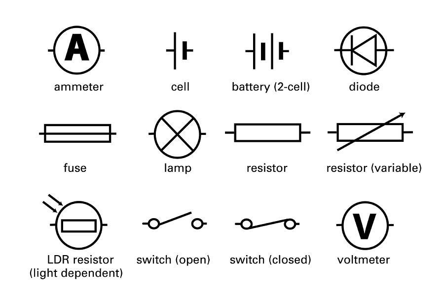
Standard Electrical Circuit Symbols Photograph by Sheila Terry Fine Art America
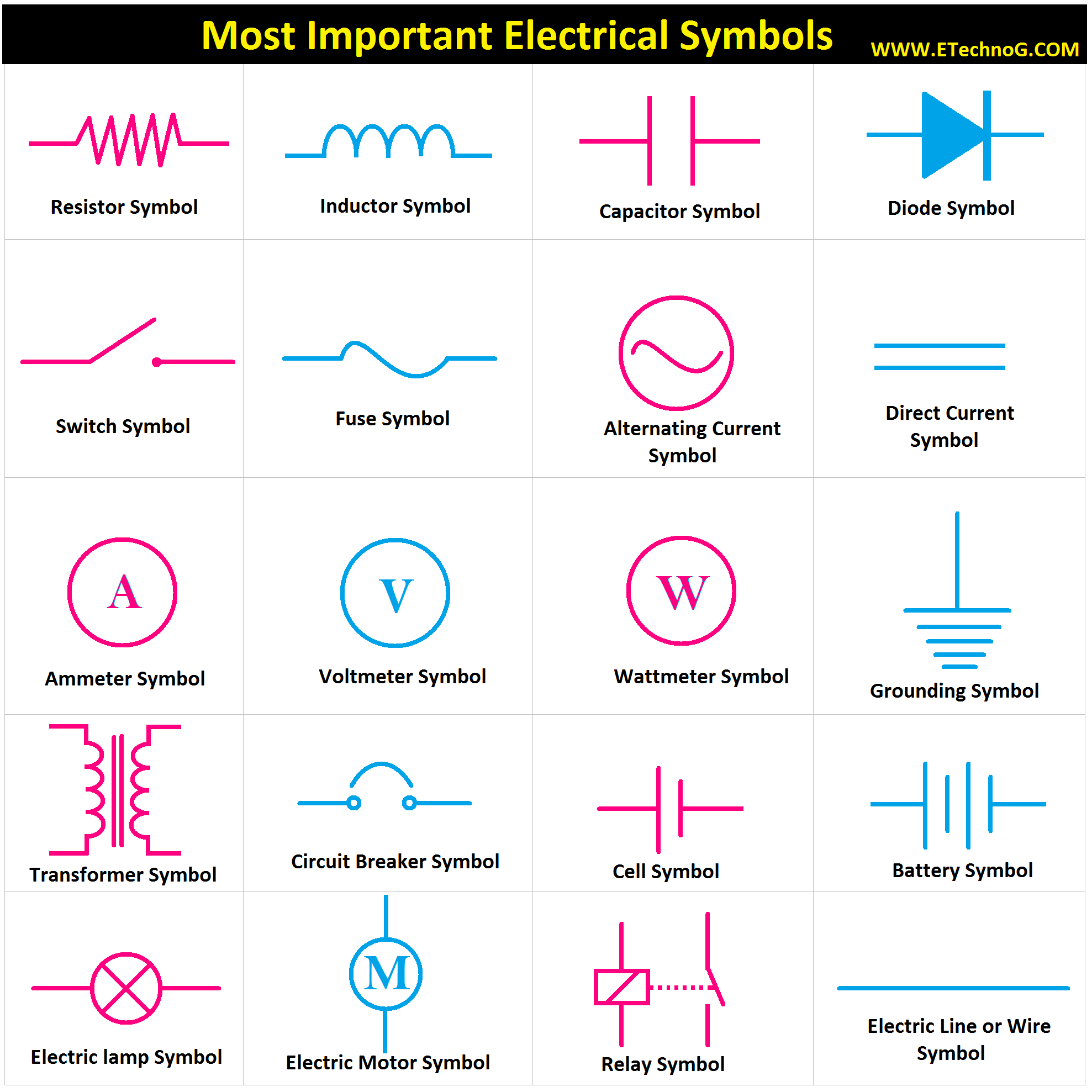
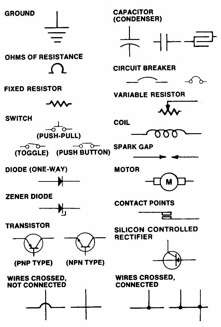
There are some standard symbols to represent the components in a circuits. This article gives some of the frequently used symbols for drawing the circuits. There are many electrical and electronic schematic symbols are used to signify basic electronic or electrical device. These are mostly we used for draw circuit diagrams.
Electrical Diagrams and Schematics Inst Tools
Units & Symbols for Electrical & Electronic Engineering The IET 2016. *Adjective only, as in a.c. motor, d.c. circuit. †As in 3-ph. Supply Ad hoc abbreviations (such as s.s.b. for single sideband) may be employed subject to an initial use in context of the full expression. Some acronyms (e.g. radar, laser) are used as nouns.
Motor Symbol Free CAD Block And AutoCAD Drawing
Play 01:06 Follow along and learn to construct a circuit. Video Transcript Drawing circuit symbols When drawing circuit diagrams, rather than drawing detailed components, we use simple.
Circuit Diagrams Symbols And Meanings
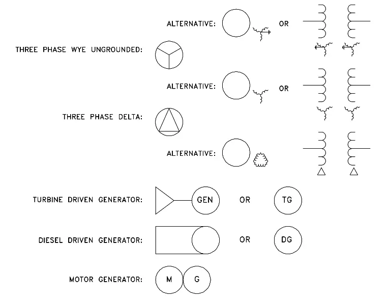
A1: To identify the piece of equipment that operates by use of electricity and is used to produce additional power. A2: The asterisk, *, shall be replaced by one of the following letter designations: C Rotary converter G Generator GP Permanent magnet generator GS Synchronous generator M Motor MG Machine capable of use as a generator or motor
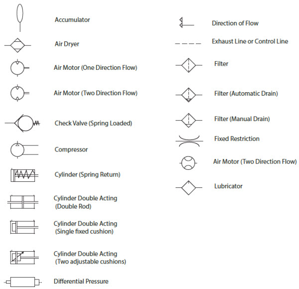
Pneumatic Circuit Symbols Explained
1 of 2 Slide 1 of 2, A circuit symbol diagram joining a cell, a switch and two bulbs., This circuit diagram joins a cell, a switch and two bulbs. Click on the next slide to see what the.
Motor Symbol Circuit Diagram
The schematic symbol for a battery is made up of short and long parallel lines. The longer line represents the positive terminal of the battery, while the shorter line represents the negative terminal: Ground Ground is the common return path of a circuit, where current returns to its source.

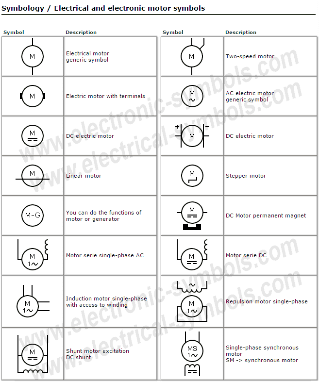
Electric Motors Symbols AC/DC, Single Phase / Three Phase Motors
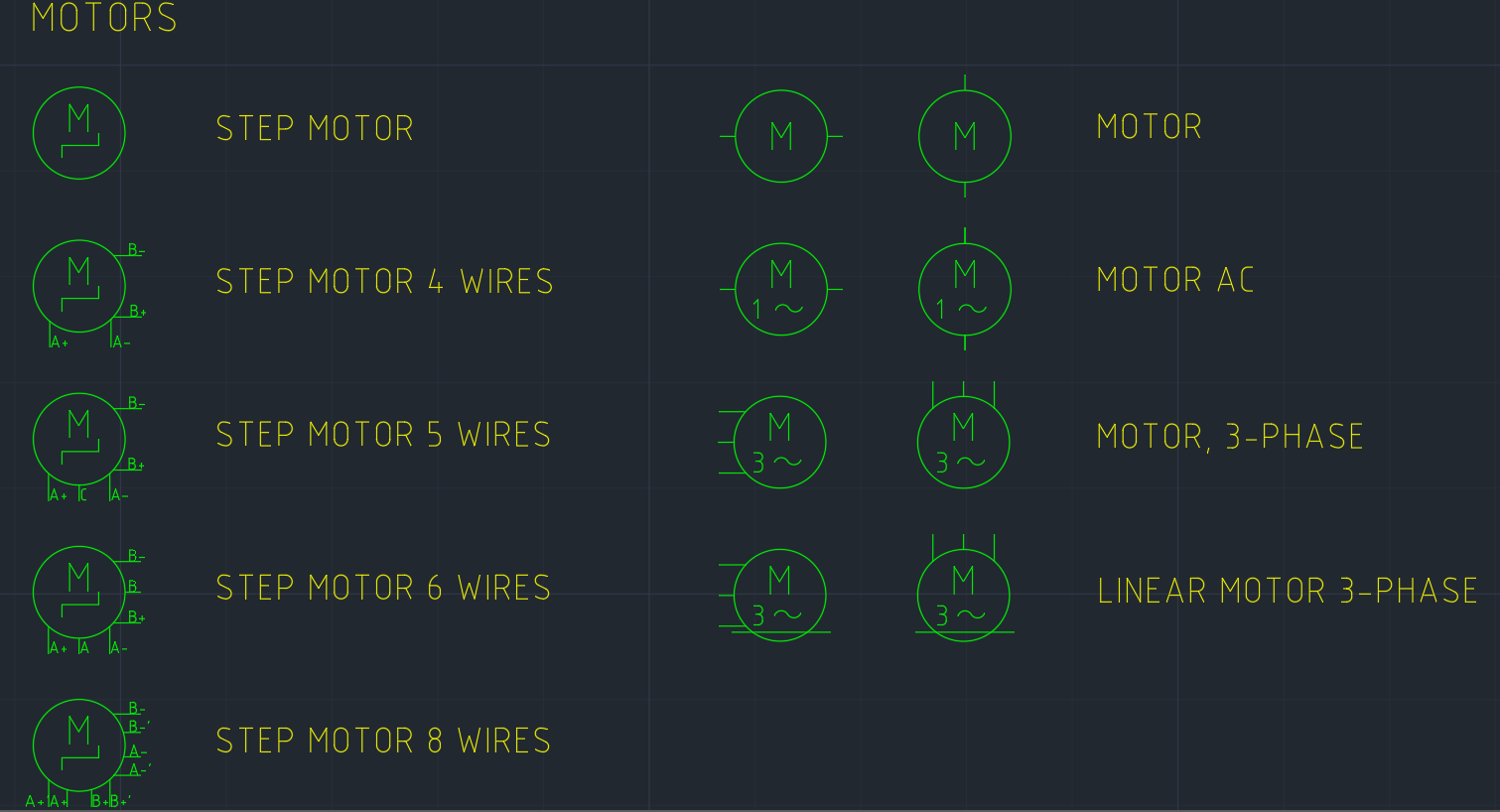
The schematic symbol for a DC motor typically consists of a circle with two lines extending from it, resembling a letter "M" or a letter "W" on its side. The circle represents the motor itself, while the lines represent the electrical connections.

Electric motor and circuit symbol, illustration Stock Image C050/8145 Science Photo Library
Circuit symbols are used in circuit diagrams which show how a circuit is connected together. The actual layout of the components is usually quite different from the circuit diagram. To build a circuit you need a different diagram showing the layout of the parts on stripboard or. printed circuit board. Wires and connections. Wires and connections.

Schematic Symbols — cip learning store
In order to provide power to the stator, a circuit symbol for motor must be used. This symbol typically includes a schematic representation of two coils connected in parallel, as well as a line that runs from one coil to another. This line is known as the "phase winding" and indicates the direction of current flow in the circuit.
Motor Wiring Symbols
Electrical symbols & electronic circuit symbols of schematic diagram - resistor, capacitor, inductor, relay, switch, wire, ground, diode, LED, transistor, power supply, antenna, lamp, logic gates,.
Símbolos Eléctricos y Electrónicos Electrical motor symbols
An electric motor is a device that converts electrical energy into mechanical energy, powering various types of machinery and appliances.. A schematic diagram is a visual representation of an electrical circuit. It uses symbols and lines to show the different components and connections within the circuit. Schematic diagrams are commonly used.
